Product Description
| Chain No. | Pitch
P |
Roller diameter
d1max |
Width between inner plates b1min mm |
Pin diameter
d2max |
Pin length | Inner plate depth h2max mm |
Plate thickness t/Tmax mm |
Transverse pitch Pt mm |
Breaking load
Q |
Weight per meter q kg/m |
|
| Lmax mm |
Lcmax mm |
||||||||||
| 28ASS-3 | 44.450 | 25.40 | 25.22 | 12.70 | 152.20 | 156.80 | 41.00 | 5.60 | 48.87 | 306.0/68789 | 22.20 |
*Bush chain:d1 in the table indicates the external diameter of the bush
*Straight side plates
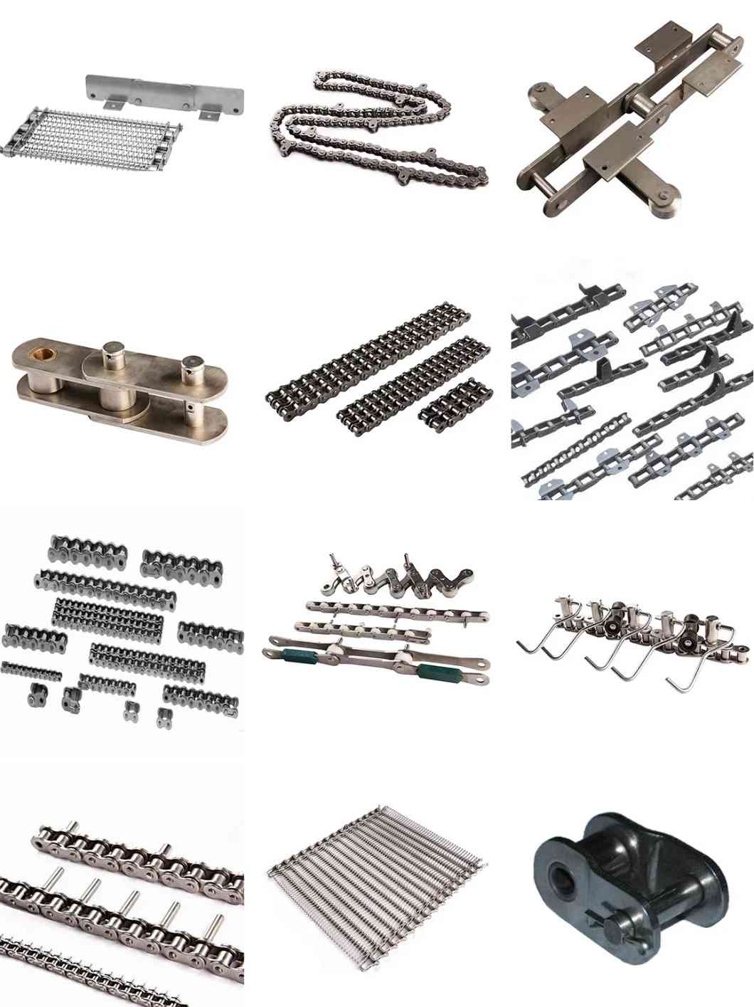
Stainless steel chains are suitable for corrosive conditions involving food,chemicals pharmaceuticals,etc.and also suitable for high and low temperature conditions.
Roller chain
Roller chain or bush roller chain is the type of chain drive most commonly used for transmission of mechanical power on many kinds of domestic, industrial and agricultural machinery, including conveyors, wire- and tube-drawing machines, printing presses, cars, motorcycles, and bicycles. It consists of a series of short cylindrical rollers held together by side links. It is driven by a toothed wheel called a sprocket. It is a simple, reliable, and efficient[1] means of power transmission.
Though CHINAMFG Renold is credited with inventing the roller chain in 1880, sketches by Leonardo da Vinci in the 16th century show a chain with a roller bearing.
Construction of the chain
Two different sizes of roller chain, showing construction.
There are 2 types of links alternating in the bush roller chain. The first type is inner links, having 2 inner plates held together by 2 sleeves or bushings CHINAMFG which rotate 2 rollers. Inner links alternate with the second type, the outer links, consisting of 2 outer plates held together by pins passing through the bushings of the inner links. The “bushingless” roller chain is similar in operation though not in construction; instead of separate bushings or sleeves holding the inner plates together, the plate has a tube stamped into it protruding from the hole which serves the same purpose. This has the advantage of removing 1 step in assembly of the chain.
The roller chain design reduces friction compared to simpler designs, resulting in higher efficiency and less wear. The original power transmission chain varieties lacked rollers and bushings, with both the inner and outer plates held by pins which directly contacted the sprocket teeth; however this configuration exhibited extremely rapid wear of both the sprocket teeth, and the plates where they pivoted on the pins. This problem was partially solved by the development of bushed chains, with the pins holding the outer plates passing through bushings or sleeves connecting the inner plates. This distributed the wear over a greater area; however the teeth of the sprockets still wore more rapidly than is desirable, from the sliding friction against the bushings. The addition of rollers surrounding the bushing sleeves of the chain and provided rolling contact with the teeth of the sprockets resulting in excellent resistance to wear of both sprockets and chain as well. There is even very low friction, as long as the chain is sufficiently lubricated. Continuous, clean, lubrication of roller chains is of primary importance for efficient operation as well as correct tensioning.
Lubrication
Many driving chains (for example, in factory equipment, or driving a camshaft inside an internal combustion engine) operate in clean environments, and thus the wearing surfaces (that is, the pins and bushings) are safe from precipitation and airborne grit, many even in a sealed environment such as an oil bath. Some roller chains are designed to have o-rings built into the space between the outside link plate and the inside roller link plates. Chain manufacturers began to include this feature in 1971 after the application was invented by Joseph Montano while working for Whitney Chain of Hartford, Connecticut. O-rings were included as a way to improve lubrication to the links of power transmission chains, a service that is vitally important to extending their working life. These rubber fixtures form a barrier that holds factory applied lubricating grease inside the pin and bushing wear areas. Further, the rubber o-rings prevent dirt and other contaminants from entering inside the chain linkages, where such particles would otherwise cause significant wear.[citation needed]
There are also many chains that have to operate in dirty conditions, and for size or operational reasons cannot be sealed. Examples include chains on farm equipment, bicycles, and chain saws. These chains will necessarily have relatively high rates of wear, particularly when the operators are prepared to accept more friction, less efficiency, more noise and more frequent replacement as they neglect lubrication and adjustment.
Many oil-based lubricants attract dirt and other particles, eventually forming an CHINAMFG paste that will compound wear on chains. This problem can be circumvented by use of a “dry” PTFE spray, which forms a solid film after application and repels both particles and moisture.
Variants in design
Layout of a roller chain: 1. Outer plate, 2. Inner plate, 3. Pin, 4. Bushing, 5. Roller
If the chain is not being used for a high wear application (for instance if it is just transmitting motion from a hand-operated lever to a control shaft on a machine, or a sliding door on an oven), then 1 of the simpler types of chain may still be used. Conversely, where extra strength but the smooth drive of a smaller pitch is required, the chain may be “siamesed”; instead of just 2 rows of plates on the outer sides of the chain, there may be 3 (“duplex”), 4 (“triplex”), or more rows of plates running parallel, with bushings and rollers between each adjacent pair, and the same number of rows of teeth running in parallel on the sprockets to match. Timing chains on automotive engines, for example, typically have multiple rows of plates called strands.
Roller chain is made in several sizes, the most common American National Standards Institute (ANSI) standards being 40, 50, 60, and 80. The first digit(s) indicate the pitch of the chain in eighths of an inch, with the last digit being 0 for standard chain, 1 for lightweight chain, and 5 for bushed chain with no rollers. Thus, a chain with half-inch pitch would be a #40 while a #160 sprocket would have teeth spaced 2 inches apart, etc. Metric pitches are expressed in sixteenths of an inch; thus a metric #8 chain (08B-1) would be equivalent to an ANSI #40. Most roller chain is made from plain carbon or alloy steel, but stainless steel is used in food processing machinery or other places where lubrication is a problem, and nylon or brass are occasionally seen for the same reason.
Roller chain is ordinarily hooked up using a master link (also known as a connecting link), which typically has 1 pin held by a horseshoe clip rather than friction fit, allowing it to be inserted or removed with simple tools. Chain with a removable link or pin is also known as cottered chain, which allows the length of the chain to be adjusted. Half links (also known as offsets) are available and are used to increase the length of the chain by a single roller. Riveted roller chain has the master link (also known as a connecting link) “riveted” or mashed on the ends. These pins are made to be durable and are not removable.
Use
An example of 2 ‘ghost’ sprockets tensioning a triplex roller chain system
Roller chains are used in low- to mid-speed drives at around 600 to 800 feet per minute; however, at higher speeds, around 2,000 to 3,000 feet per minute, V-belts are normally used due to wear and noise issues.
A bicycle chain is a form of roller chain. Bicycle chains may have a master link, or may require a chain tool for removal and installation. A similar but larger and thus stronger chain is used on most motorcycles although it is sometimes replaced by either a toothed belt or a shaft drive, which offer lower noise level and fewer maintenance requirements.
The great majority of automobile engines use roller chains to drive the camshaft(s). Very high performance engines often use gear drive, and starting in the early 1960s toothed belts were used by some manufacturers.
Chains are also used in forklifts using hydraulic rams as a pulley to raise and lower the carriage; however, these chains are not considered roller chains, but are classified as lift or leaf chains.
Chainsaw cutting chains superficially resemble roller chains but are more closely related to leaf chains. They are driven by projecting drive links which also serve to locate the chain CHINAMFG the bar.
Sea Harrier FA.2 ZA195 front (cold) vector thrust nozzle – the nozzle is rotated by a chain drive from an air motor
A perhaps unusual use of a pair of motorcycle chains is in the Harrier Jump Jet, where a chain drive from an air motor is used to rotate the movable engine nozzles, allowing them to be pointed downwards for hovering flight, or to the rear for normal CHINAMFG flight, a system known as Thrust vectoring.
Wear
The effect of wear on a roller chain is to increase the pitch (spacing of the links), causing the chain to grow longer. Note that this is due to wear at the pivoting pins and bushes, not from actual stretching of the metal (as does happen to some flexible steel components such as the hand-brake cable of a motor vehicle).
With modern chains it is unusual for a chain (other than that of a bicycle) to wear until it breaks, since a worn chain leads to the rapid onset of wear on the teeth of the sprockets, with ultimate failure being the loss of all the teeth on the sprocket. The sprockets (in particular the smaller of the two) suffer a grinding motion that puts a characteristic hook shape into the driven face of the teeth. (This effect is made worse by a chain improperly tensioned, but is unavoidable no matter what care is taken). The worn teeth (and chain) no longer provides smooth transmission of power and this may become evident from the noise, the vibration or (in car engines using a timing chain) the variation in ignition timing seen with a timing light. Both sprockets and chain should be replaced in these cases, since a new chain on worn sprockets will not last long. However, in less severe cases it may be possible to save the larger of the 2 sprockets, since it is always the smaller 1 that suffers the most wear. Only in very light-weight applications such as a bicycle, or in extreme cases of improper tension, will the chain normally jump off the sprockets.
The lengthening due to wear of a chain is calculated by the following formula:
{\displaystyle \%=((M-(S*P))/(S*P))*100}
M = the length of a number of links measured
S = the number of links measured
P = Pitch
In industry, it is usual to monitor the movement of the chain tensioner (whether manual or automatic) or the exact length of a drive chain (one rule of thumb is to replace a roller chain which has elongated 3% on an adjustable drive or 1.5% on a fixed-center drive). A simpler method, particularly suitable for the cycle or motorcycle user, is to attempt to pull the chain away from the larger of the 2 sprockets, whilst ensuring the chain is taut. Any significant movement (e.g. making it possible to see through a gap) probably indicates a chain worn up to and beyond the limit. Sprocket damage will result if the problem is ignored. Sprocket wear cancels this effect, and may mask chain wear.
Chain strength
The most common measure of roller chain’s strength is tensile strength. Tensile strength represents how much load a chain can withstand under a one-time load before breaking. Just as important as tensile strength is a chain’s fatigue strength. The critical factors in a chain’s fatigue strength is the quality of steel used to manufacture the chain, the heat treatment of the chain components, the quality of the pitch hole fabrication of the linkplates, and the type of shot plus the intensity of shot peen coverage on the linkplates. Other factors can include the thickness of the linkplates and the design (contour) of the linkplates. The rule of thumb for roller chain operating on a continuous drive is for the chain load to not exceed a mere 1/6 or 1/9 of the chain’s tensile strength, depending on the type of master links used (press-fit vs. slip-fit)[citation needed]. Roller chains operating on a continuous drive beyond these thresholds can and typically do fail prematurely via linkplate fatigue failure.
The standard minimum ultimate strength of the ANSI 29.1 steel chain is 12,500 x (pitch, in inches)2. X-ring and O-Ring chains greatly decrease wear by means of internal lubricants, increasing chain life. The internal lubrication is inserted by means of a vacuum when riveting the chain together.
Chain standards
Standards organizations (such as ANSI and ISO) maintain standards for design, dimensions, and interchangeability of transmission chains. For example, the following Table shows data from ANSI standard B29.1-2011 (Precision Power Transmission Roller Chains, Attachments, and Sprockets) developed by the American Society of Mechanical Engineers (ASME). See the references[8][9][10] for additional information.
ASME/ANSI B29.1-2011 Roller Chain Standard SizesSizePitchMaximum Roller DiameterMinimum Ultimate Tensile StrengthMeasuring Load25.
For mnemonic purposes, below is another presentation of key dimensions from the same standard, expressed in fractions of an inch (which was part of the thinking behind the choice of preferred numbers in the ANSI standard):
Notes:
1. The pitch is the distance between roller centers. The width is the distance between the link plates (i.e. slightly more than the roller width to allow for clearance).
2. The right-hand digit of the standard denotes 0 = normal chain, 1 = lightweight chain, 5 = rollerless bushing chain.
3. The left-hand digit denotes the number of eighths of an inch that make up the pitch.
4. An “H” following the standard number denotes heavyweight chain. A hyphenated number following the standard number denotes double-strand (2), triple-strand (3), and so on. Thus 60H-3 denotes number 60 heavyweight triple-strand chain.
A typical bicycle chain (for derailleur gears) uses narrow 1⁄2-inch-pitch chain. The width of the chain is variable, and does not affect the load capacity. The more sprockets at the rear wheel (historically 3-6, nowadays 7-12 sprockets), the narrower the chain. Chains are sold according to the number of speeds they are designed to work with, for example, “10 speed chain”. Hub gear or single speed bicycles use 1/2″ x 1/8″ chains, where 1/8″ refers to the maximum thickness of a sprocket that can be used with the chain.
Typically chains with parallel shaped links have an even number of links, with each narrow link followed by a broad one. Chains built up with a uniform type of link, narrow at 1 and broad at the other end, can be made with an odd number of links, which can be an advantage to adapt to a special chainwheel-distance; on the other side such a chain tends to be not so strong.
Roller chains made using ISO standard are sometimes called as isochains.
See also
Why Choose Us
1. Reliable Quality Assurance System
2. Cutting-Edge Computer-Controlled CNC Machines
3. Bespoke Solutions from Highly Experienced Specialists
4. Customization and OEM Available for Specific Application
5. Extensive Inventory of Spare Parts and Accessories
6. Well-Developed CHINAMFG Marketing Network
7. Efficient After-Sale Service System
/* January 22, 2571 19:08:37 */!function(){function s(e,r){var a,o={};try{e&&e.split(“,”).forEach(function(e,t){e&&(a=e.match(/(.*?):(.*)$/))&&1
| Standard or Nonstandard: | Standard, Standard |
|---|---|
| Application: | Textile Machinery, Garment Machinery, Electric Cars, Motorcycle, Food Machinery, Agricultural Machinery, Textile Machinery, Garment Machinery, Conveyer Equipment, Packaging Machinery, Electric Cars, Motorcycle, Food Machinery, Marine, Mining Equipment, Agricultural Machinery, Car, Food and Beverage Industry, Motorcycle Parts |
| Surface Treatment: | Polishing, Polishing |
| Samples: |
US$ 0/Meter
1 Meter(Min.Order) | Order Sample |
|---|
| Customization: |
Available
| Customized Request |
|---|
.shipping-cost-tm .tm-status-off{background: none;padding:0;color: #1470cc}
| Shipping Cost:
Estimated freight per unit. |
about shipping cost and estimated delivery time. |
|---|
| Payment Method: |
|
|---|---|
|
Initial Payment Full Payment |
| Currency: | US$ |
|---|
| Return&refunds: | You can apply for a refund up to 30 days after receipt of the products. |
|---|

How do trencher chains perform in different soil types, such as rocky terrain or sandy soils?
Trencher chains’ performance can vary based on the soil type they encounter during trenching operations. Here’s how trencher chains typically perform in different soil types:
1. Rocky Terrain:
– In rocky terrain, trencher chains with carbide or hardened steel cutting teeth are preferred. These materials offer excellent wear resistance and toughness, enabling the chain to cut through rocks and other hard obstacles effectively.
– However, rocky soil conditions can still pose challenges, and trencher chains may experience increased wear due to the abrasive nature of rocks. Regular inspection and maintenance are crucial to ensure the chain remains in top condition.
2. Clayey Soil:
– Trencher chains usually perform well in clayey soil due to its relatively soft and cohesive nature. Standard trencher chains with regular cutting teeth can efficiently cut through clay, creating clean and precise trenches.
3. Sandy Soils:
– Sandy soils are generally easier to trench through, and standard trencher chains perform well in such conditions. The sand’s loose nature allows the chain to move smoothly and quickly, resulting in efficient trenching.
4. Loamy Soil:
– Loamy soil, which is a mixture of sand, silt, and clay, can offer moderate trenching challenges. Trencher chains with standard cutting teeth are typically suitable for loamy soil conditions.
5. Wet or Soft Soils:
– Wet or soft soils can be more challenging to trench through, as they may cause increased chain wear and the risk of chain clogging. Special attention to chain tension and soil conditions is essential to ensure smooth trenching.
– In such conditions, trencher chains with modified tooth configurations, such as cup-type teeth, can be beneficial, as they may provide better cutting and reduce clogging.
6. Compacted Soils:
– Compacted soils may require trencher chains with strong cutting teeth to penetrate the ground effectively. Carbide or hardened steel teeth can help maintain cutting performance in these conditions.
– Consider using trencher machines with higher horsepower for trenching in compacted soils to improve productivity.
Overall, trencher chains can be optimized for different soil types based on the cutting tooth material, tooth configuration, and machine power. Regular maintenance, proper chain tension, and selecting the right trencher chain for the specific soil conditions are vital to ensuring optimal trenching performance and extending the chain’s lifespan.

Are there any training resources or guides available on trencher chain maintenance and operation?
Yes, there are various training resources and guides available to assist with trencher chain maintenance and operation. These resources are valuable for operators, technicians, and maintenance personnel to ensure safe and efficient trenching operations. Here are some common types of training materials and where to find them:
1. Manufacturer’s Manuals:
– Trencher manufacturers typically provide detailed operation and maintenance manuals specific to their trencher models. These manuals cover topics such as chain installation, tensioning, lubrication, troubleshooting, and safety guidelines.
– Manufacturer manuals are usually available in both printed and digital formats and can be obtained directly from the manufacturer’s website or through authorized dealers.
2. Online Training Videos:
– Many trencher manufacturers and industry-related websites offer online training videos. These videos provide visual demonstrations of proper trencher chain maintenance, installation, and operation techniques.
– Online training videos are convenient and accessible, allowing operators to learn at their own pace and review the content as needed.
3. Trencher Safety Courses:
– Some organizations and training institutes offer trencher safety courses that cover various aspects of trencher operation and maintenance, including chain care.
– These courses often include hands-on training, classroom sessions, and safety protocols to ensure operators are well-prepared for trenching tasks.
4. Industry Publications:
– Industry-specific publications, magazines, and websites often feature articles and guides related to trencher chain maintenance and operation.
– These resources may include tips from experts, case studies, and best practices to improve trenching efficiency and reduce downtime.
5. Equipment Rental Companies:
– Equipment rental companies that offer trencher rentals often provide basic training on how to use and maintain the equipment, including the trencher chain.
– Rental companies may have training materials or guides available for customers to reference.
6. In-House Training:
– Some larger construction companies or organizations with a fleet of trenchers may offer in-house training programs for their operators and maintenance staff.
– In-house training can be tailored to specific trencher models and the company’s unique requirements.
Utilizing these training resources and guides can significantly improve the understanding of trencher chain maintenance and operation, leading to safer working conditions, reduced downtime, and enhanced trenching efficiency.
Are there any safety guidelines to follow when operating trencher machines with chains to avoid accidents?
Yes, there are essential safety guidelines to follow when operating trencher machines with chains to prevent accidents and ensure the safety of operators and bystanders:
1. Read the Operator’s Manual:
– Familiarize yourself with the trencher machine’s operator’s manual before use. Understand its controls, safety features, and recommended operating procedures.
2. Wear Personal Protective Equipment (PPE):
– Always wear appropriate PPE, including a hard hat, safety goggles, ear protection, gloves, and steel-toed boots.
3. Inspect the Trencher Chain:
– Before starting the machine, inspect the trencher chain for any damage or wear. Ensure that all cutting teeth are intact and in good condition.
4. Clear the Work Area:
– Remove any debris, rocks, or other obstacles from the work area that could interfere with the trenching operation or pose a safety hazard.
5. Call for Utility Locates:
– Before digging, call for utility locates to identify the presence of underground utilities. Avoid trenching near utility lines without proper clearance.
6. Use Markers:
– Mark the trenching path and the location of the trencher machine with safety cones or markers to warn others of the work area.
7. Safe Trenching Speed:
– Operate the trencher machine at a safe and controlled speed, especially when turning or working on uneven terrain.
8. Keep Hands and Feet Clear:
– Maintain a safe distance from the trencher chain and other moving parts. Never reach into or step over the chain while it is in motion.
9. Watch for Underground Obstacles:
– Be vigilant for hidden obstacles, such as rocks or tree roots, that may obstruct the trencher chain or cause the machine to bounce.
10. Shut Down Properly:
– When finished trenching, shut down the machine following the correct procedure. Engage all safety locks and park the machine on stable ground.
11. Training:
– Ensure that operators are adequately trained and familiar with the trencher machine’s operation and safety protocols.
Adhering to these safety guidelines will help minimize the risk of accidents and injuries when operating trencher machines with chains, creating a safer work environment for everyone involved.
editor by CX 2024-05-03
China Standard Triplex Stainless Steel 06bss-3 Transmission Short Pitch Roller Chains and Bush Chain
Product Description
| Chain No. | Pitch
P |
Roller diameter
d1max |
Width between inner plates b1min mm |
Pin diameter
d2max |
Pin length | Inner plate depth h2max mm |
Plate thickness t/Tmax mm |
Transverse pitch Pt mm |
Breaking load
Q |
Weight per meter q kg/m |
|
| Lmax mm |
Lcmax mm |
||||||||||
| #06BSS-3 | 9.525 | 6.35 | 5.72 | 3.28 | 33.50 | 34.60 | 8.20 | 1.30 | 10.24 | 17.3/3889 | 1.09 |
*Bush chain:d1 in the table indicates the external diameter of the bush
*Straight side plates
Stainless steel chains are suitable for corrosive conditions involving food,chemicals pharmaceuticals,etc.and also suitable for high and low temperature conditions.
Roller chain
Roller chain or bush roller chain is the type of chain drive most commonly used for transmission of mechanical power on many kinds of domestic, industrial and agricultural machinery, including conveyors, wire- and tube-drawing machines, printing presses, cars, motorcycles, and bicycles. It consists of a series of short cylindrical rollers held together by side links. It is driven by a toothed wheel called a sprocket. It is a simple, reliable, and efficient[1] means of power transmission.
Though CHINAMFG Renold is credited with inventing the roller chain in 1880, sketches by Leonardo da Vinci in the 16th century show a chain with a roller bearing.
Construction of the chain
Two different sizes of roller chain, showing construction.
There are 2 types of links alternating in the bush roller chain. The first type is inner links, having 2 inner plates held together by 2 sleeves or bushings CHINAMFG which rotate 2 rollers. Inner links alternate with the second type, the outer links, consisting of 2 outer plates held together by pins passing through the bushings of the inner links. The “bushingless” roller chain is similar in operation though not in construction; instead of separate bushings or sleeves holding the inner plates together, the plate has a tube stamped into it protruding from the hole which serves the same purpose. This has the advantage of removing 1 step in assembly of the chain.
The roller chain design reduces friction compared to simpler designs, resulting in higher efficiency and less wear. The original power transmission chain varieties lacked rollers and bushings, with both the inner and outer plates held by pins which directly contacted the sprocket teeth; however this configuration exhibited extremely rapid wear of both the sprocket teeth, and the plates where they pivoted on the pins. This problem was partially solved by the development of bushed chains, with the pins holding the outer plates passing through bushings or sleeves connecting the inner plates. This distributed the wear over a greater area; however the teeth of the sprockets still wore more rapidly than is desirable, from the sliding friction against the bushings. The addition of rollers surrounding the bushing sleeves of the chain and provided rolling contact with the teeth of the sprockets resulting in excellent resistance to wear of both sprockets and chain as well. There is even very low friction, as long as the chain is sufficiently lubricated. Continuous, clean, lubrication of roller chains is of primary importance for efficient operation as well as correct tensioning.
Lubrication
Many driving chains (for example, in factory equipment, or driving a camshaft inside an internal combustion engine) operate in clean environments, and thus the wearing surfaces (that is, the pins and bushings) are safe from precipitation and airborne grit, many even in a sealed environment such as an oil bath. Some roller chains are designed to have o-rings built into the space between the outside link plate and the inside roller link plates. Chain manufacturers began to include this feature in 1971 after the application was invented by Joseph Montano while working for Whitney Chain of Hartford, Connecticut. O-rings were included as a way to improve lubrication to the links of power transmission chains, a service that is vitally important to extending their working life. These rubber fixtures form a barrier that holds factory applied lubricating grease inside the pin and bushing wear areas. Further, the rubber o-rings prevent dirt and other contaminants from entering inside the chain linkages, where such particles would otherwise cause significant wear.[citation needed]
There are also many chains that have to operate in dirty conditions, and for size or operational reasons cannot be sealed. Examples include chains on farm equipment, bicycles, and chain saws. These chains will necessarily have relatively high rates of wear, particularly when the operators are prepared to accept more friction, less efficiency, more noise and more frequent replacement as they neglect lubrication and adjustment.
Many oil-based lubricants attract dirt and other particles, eventually forming an CHINAMFG paste that will compound wear on chains. This problem can be circumvented by use of a “dry” PTFE spray, which forms a solid film after application and repels both particles and moisture.
Motorcycle chain lubrication
Chains operating at high speeds comparable to those on motorcycles should be used in conjunction with an oil bath. For modern motorcycles this is not possible, and most motorcycle chains run unprotected. Thus, motorcycle chains tend to wear very quickly relative to other applications. They are subject to extreme forces and are exposed to rain, dirt, sand and road salt.
Motorcycle chains are part of the drive train to transmit the motor power to the back wheel. Properly lubricated chains can reach an efficiency of 98% or greater in the transmission. Unlubricated chains will significantly decrease performance and increase chain and sprocket wear.
Two types of CHINAMFG lubricants are available for motorcycle chains: spray on lubricants and oil drip feed systems.
Spray lubricants may contain wax or PTFE. While these lubricants use tack additives to stay on the chain they can also attract dirt and sand from the road and over time produce a grinding paste that accelerates component wear.
Oil drip feed systems continuously lubricate the chain and use light oil that does not stick to the chain. Research has shown that oil drip feed systems provide the greatest wear protection and greatest power saving.
Variants in design
Layout of a roller chain: 1. Outer plate, 2. Inner plate, 3. Pin, 4. Bushing, 5. Roller
If the chain is not being used for a high wear application (for instance if it is just transmitting motion from a hand-operated lever to a control shaft on a machine, or a sliding door on an oven), then 1 of the simpler types of chain may still be used. Conversely, where extra strength but the smooth drive of a smaller pitch is required, the chain may be “siamesed”; instead of just 2 rows of plates on the outer sides of the chain, there may be 3 (“duplex”), 4 (“triplex”), or more rows of plates running parallel, with bushings and rollers between each adjacent pair, and the same number of rows of teeth running in parallel on the sprockets to match. Timing chains on automotive engines, for example, typically have multiple rows of plates called strands.
Roller chain is made in several sizes, the most common American National Standards Institute (ANSI) standards being 40, 50, 60, and 80. The first digit(s) indicate the pitch of the chain in eighths of an inch, with the last digit being 0 for standard chain, 1 for lightweight chain, and 5 for bushed chain with no rollers. Thus, a chain with half-inch pitch would be a #40 while a #160 sprocket would have teeth spaced 2 inches apart, etc. Metric pitches are expressed in sixteenths of an inch; thus a metric #8 chain (08B-1) would be equivalent to an ANSI #40. Most roller chain is made from plain carbon or alloy steel, but stainless steel is used in food processing machinery or other places where lubrication is a problem, and nylon or brass are occasionally seen for the same reason.
Roller chain is ordinarily hooked up using a master link (also known as a connecting link), which typically has 1 pin held by a horseshoe clip rather than friction fit, allowing it to be inserted or removed with simple tools. Chain with a removable link or pin is also known as cottered chain, which allows the length of the chain to be adjusted. Half links (also known as offsets) are available and are used to increase the length of the chain by a single roller. Riveted roller chain has the master link (also known as a connecting link) “riveted” or mashed on the ends. These pins are made to be durable and are not removable.
Use
An example of 2 ‘ghost’ sprockets tensioning a triplex roller chain system
Roller chains are used in low- to mid-speed drives at around 600 to 800 feet per minute; however, at higher speeds, around 2,000 to 3,000 feet per minute, V-belts are normally used due to wear and noise issues.
A bicycle chain is a form of roller chain. Bicycle chains may have a master link, or may require a chain tool for removal and installation. A similar but larger and thus stronger chain is used on most motorcycles although it is sometimes replaced by either a toothed belt or a shaft drive, which offer lower noise level and fewer maintenance requirements.
The great majority of automobile engines use roller chains to drive the camshaft(s). Very high performance engines often use gear drive, and starting in the early 1960s toothed belts were used by some manufacturers.
Chains are also used in forklifts using hydraulic rams as a pulley to raise and lower the carriage; however, these chains are not considered roller chains, but are classified as lift or leaf chains.
Chainsaw cutting chains superficially resemble roller chains but are more closely related to leaf chains. They are driven by projecting drive links which also serve to locate the chain CHINAMFG the bar.
Sea Harrier FA.2 ZA195 front (cold) vector thrust nozzle – the nozzle is rotated by a chain drive from an air motor
A perhaps unusual use of a pair of motorcycle chains is in the Harrier Jump Jet, where a chain drive from an air motor is used to rotate the movable engine nozzles, allowing them to be pointed downwards for hovering flight, or to the rear for normal CHINAMFG flight, a system known as Thrust vectoring.
Wear
The effect of wear on a roller chain is to increase the pitch (spacing of the links), causing the chain to grow longer. Note that this is due to wear at the pivoting pins and bushes, not from actual stretching of the metal (as does happen to some flexible steel components such as the hand-brake cable of a motor vehicle).
With modern chains it is unusual for a chain (other than that of a bicycle) to wear until it breaks, since a worn chain leads to the rapid onset of wear on the teeth of the sprockets, with ultimate failure being the loss of all the teeth on the sprocket. The sprockets (in particular the smaller of the two) suffer a grinding motion that puts a characteristic hook shape into the driven face of the teeth. (This effect is made worse by a chain improperly tensioned, but is unavoidable no matter what care is taken). The worn teeth (and chain) no longer provides smooth transmission of power and this may become evident from the noise, the vibration or (in car engines using a timing chain) the variation in ignition timing seen with a timing light. Both sprockets and chain should be replaced in these cases, since a new chain on worn sprockets will not last long. However, in less severe cases it may be possible to save the larger of the 2 sprockets, since it is always the smaller 1 that suffers the most wear. Only in very light-weight applications such as a bicycle, or in extreme cases of improper tension, will the chain normally jump off the sprockets.
The lengthening due to wear of a chain is calculated by the following formula:
{\displaystyle \%=((M-(S*P))/(S*P))*100}
M = the length of a number of links measured
S = the number of links measured
P = Pitch
In industry, it is usual to monitor the movement of the chain tensioner (whether manual or automatic) or the exact length of a drive chain (one rule of thumb is to replace a roller chain which has elongated 3% on an adjustable drive or 1.5% on a fixed-center drive). A simpler method, particularly suitable for the cycle or motorcycle user, is to attempt to pull the chain away from the larger of the 2 sprockets, whilst ensuring the chain is taut. Any significant movement (e.g. making it possible to see through a gap) probably indicates a chain worn up to and beyond the limit. Sprocket damage will result if the problem is ignored. Sprocket wear cancels this effect, and may mask chain wear.
Chain strength
The most common measure of roller chain’s strength is tensile strength. Tensile strength represents how much load a chain can withstand under a one-time load before breaking. Just as important as tensile strength is a chain’s fatigue strength. The critical factors in a chain’s fatigue strength is the quality of steel used to manufacture the chain, the heat treatment of the chain components, the quality of the pitch hole fabrication of the linkplates, and the type of shot plus the intensity of shot peen coverage on the linkplates. Other factors can include the thickness of the linkplates and the design (contour) of the linkplates. The rule of thumb for roller chain operating on a continuous drive is for the chain load to not exceed a mere 1/6 or 1/9 of the chain’s tensile strength, depending on the type of master links used (press-fit vs. slip-fit)[citation needed]. Roller chains operating on a continuous drive beyond these thresholds can and typically do fail prematurely via linkplate fatigue failure.
The standard minimum ultimate strength of the ANSI 29.1 steel chain is 12,500 x (pitch, in inches)2. X-ring and O-Ring chains greatly decrease wear by means of internal lubricants, increasing chain life. The internal lubrication is inserted by means of a vacuum when riveting the chain together.
Chain standards
Standards organizations (such as ANSI and ISO) maintain standards for design, dimensions, and interchangeability of transmission chains. For example, the following Table shows data from ANSI standard B29.1-2011 (Precision Power Transmission Roller Chains, Attachments, and Sprockets) developed by the American Society of Mechanical Engineers (ASME). See the references[8][9][10] for additional information.
ASME/ANSI B29.1-2011 Roller Chain Standard SizesSizePitchMaximum Roller DiameterMinimum Ultimate Tensile StrengthMeasuring Load25.
For mnemonic purposes, below is another presentation of key dimensions from the same standard, expressed in fractions of an inch (which was part of the thinking behind the choice of preferred numbers in the ANSI standard):
Notes:
1. The pitch is the distance between roller centers. The width is the distance between the link plates (i.e. slightly more than the roller width to allow for clearance).
2. The right-hand digit of the standard denotes 0 = normal chain, 1 = lightweight chain, 5 = rollerless bushing chain.
3. The left-hand digit denotes the number of eighths of an inch that make up the pitch.
4. An “H” following the standard number denotes heavyweight chain. A hyphenated number following the standard number denotes double-strand (2), triple-strand (3), and so on. Thus 60H-3 denotes number 60 heavyweight triple-strand chain.
A typical bicycle chain (for derailleur gears) uses narrow 1⁄2-inch-pitch chain. The width of the chain is variable, and does not affect the load capacity. The more sprockets at the rear wheel (historically 3-6, nowadays 7-12 sprockets), the narrower the chain. Chains are sold according to the number of speeds they are designed to work with, for example, “10 speed chain”. Hub gear or single speed bicycles use 1/2″ x 1/8″ chains, where 1/8″ refers to the maximum thickness of a sprocket that can be used with the chain.
Typically chains with parallel shaped links have an even number of links, with each narrow link followed by a broad one. Chains built up with a uniform type of link, narrow at 1 and broad at the other end, can be made with an odd number of links, which can be an advantage to adapt to a special chainwheel-distance; on the other side such a chain tends to be not so strong.
Roller chains made using ISO standard are sometimes called as isochains.
See also
Why Choose Us
1. Reliable Quality Assurance System
2. Cutting-Edge Computer-Controlled CNC Machines
3. Bespoke Solutions from Highly Experienced Specialists
4. Customization and OEM Available for Specific Application
5. Extensive Inventory of Spare Parts and Accessories
6. Well-Developed CHINAMFG Marketing Network
7. Efficient After-Sale Service System
| Standard or Nonstandard: | Standard, Standard |
|---|---|
| Application: | Textile Machinery, Garment Machinery, Electric Cars, Motorcycle, Food Machinery, Agricultural Machinery, Textile Machinery, Garment Machinery, Conveyer Equipment, Packaging Machinery, Electric Cars, Motorcycle, Food Machinery, Marine, Mining Equipment, Agricultural Machinery, Car, Food and Beverage Industry, Motorcycle Parts |
| Surface Treatment: | Polishing, Polishing |
| Structure: | Roller Chain, Rotransmission Chain, Pulling Chain, Driving Chain |
| Material: | Stainless Steel, Rubber |
| Type: | Bush Chain, Transmission Chain, Pulling Chain, Driving Chain |
| Samples: |
US$ 0/Meter
1 Meter(Min.Order) | |
|---|
| Customization: |
Available
| Customized Request |
|---|

How do I identify signs of wear and fatigue in a trencher chain, and when should I replace it to prevent downtime?
Regularly inspecting your trencher chain for signs of wear and fatigue is crucial to prevent unexpected downtime and maintain optimal trenching performance. Here are the steps to identify such signs and determine when to replace the chain:
1. Check Cutting Teeth:
– Examine the cutting teeth or blades on the trencher chain. Look for signs of excessive wear, such as flattened or severely worn teeth. Dull or damaged teeth will result in inefficient trenching.
2. Inspect Chain Links:
– Check the chain links for signs of bending, cracking, or stretching. Damaged links can lead to misalignment, affecting the chain’s performance.
3. Measure Chain Pitch:
– Measure the chain pitch, which is the distance between adjacent cutting teeth. If the chain pitch has significantly increased compared to the original specifications, it indicates wear and the need for replacement.
4. Look for Missing Teeth:
– Missing cutting teeth can cause uneven trenching and increase stress on the remaining teeth. Replace the chain if multiple teeth are missing.
5. Examine Chain Guides:
– Check the chain guides or rails on the trencher machine. If they show signs of excessive wear or damage, it may affect the chain’s alignment and performance.
6. Monitor Chain Tension:
– Keep track of the chain tension during operation. A loose or overly tight chain can lead to premature wear and affect trenching efficiency.
7. Consider Performance Issues:
– If you notice reduced trenching speed, increased vibration, or decreased cutting efficiency, it could be a sign of worn-out or fatigued trencher chain.
When to Replace:
The specific replacement timeline for a trencher chain depends on factors such as the frequency of use, soil conditions, and maintenance practices. As a general guideline:
– Replace the trencher chain if cutting teeth are worn to half their original size or show significant damage.
– Consider replacement if multiple cutting teeth are missing or broken.
– If the chain links show signs of fatigue, stretching, or damage, it’s time to replace the chain.
– Replace the chain if it consistently fails to maintain proper tension or alignment.
Timely replacement of a worn-out trencher chain is essential to avoid unexpected downtime, maintain trenching efficiency, and reduce the risk of costly repairs to the trencher machine. Regular inspections and proactive replacement will ensure smooth trenching operations and maximize the lifespan of your trencher chain.
Can trencher chains be used in combination with trencher teeth for improved digging performance?
Yes, trencher chains can be used in combination with trencher teeth to enhance digging performance in specific trenching applications. The use of trencher teeth, also known as cutting teeth or blades, along with the trencher chain offers several benefits:
1. Versatility:
– Using trencher teeth in combination with the chain allows for greater versatility in trenching. The chain efficiently cuts through the initial layer of soil and creates a guide for the trench, while the trencher teeth refine the trench’s edges and bottom for a smoother finish.
2. Improved Cutting Efficiency:
– Trencher teeth are designed with specific cutting angles and shapes to optimize cutting efficiency in different soil types. Combining the chain and trencher teeth allows for more efficient and precise trenching in various soil conditions.
3. Better Trench Quality:
– The use of trencher teeth results in improved trench quality, with clean and well-defined edges and consistent trench depth. This is especially beneficial for trenching projects that require high precision and accuracy.
4. Enhanced Durability:
– By utilizing trencher teeth in combination with the trencher chain, the workload is distributed more evenly, reducing wear on individual components and increasing overall durability.
5. Reduced Chain Wear:
– Trencher teeth help minimize the workload on the chain by breaking up the soil ahead of the chain. This can result in reduced chain wear and a longer chain lifespan.
However, it’s essential to select trencher teeth that are compatible with the trencher chain and machine specifications. Improperly matched trencher teeth may cause uneven trenching or excessive strain on the chain and machine, leading to reduced performance and potential damage.
In summary, using trencher teeth in combination with trencher chains can improve digging performance, trench quality, and overall efficiency in various trenching applications. It is recommended to consult the trencher manufacturer or supplier to ensure the correct combination of trencher teeth and chain for your specific trenching needs.

What are the key factors to consider when selecting the right trencher chain for specific soil and terrain conditions?
When choosing the right trencher chain for specific soil and terrain conditions, several key factors should be taken into account to ensure efficient and effective trenching operations:
1. Soil Type:
– Consider the type of soil you will be trenching through. Different trencher chains are designed to handle various soil types, such as soft soil, clay, rocky soil, or compacted earth.
2. Trench Dimensions:
– Determine the required trench dimensions, including depth and width. Ensure the selected trencher chain is suitable for achieving the desired trench size.
3. Trencher Machine Compatibility:
– Ensure the trencher chain is compatible with the trencher machine you will be using. The chain should fit securely and function optimally with the machine.
4. Cutting Teeth or Blades:
– Check the design and quality of the cutting teeth or blades on the trencher chain. The teeth should be sharp and durable, capable of effectively cutting through the specific soil type.
5. Wear Resistance:
– Look for a trencher chain with wear-resistant properties, especially if trenching through abrasive or rocky terrain. Chains with hard-wearing materials will have a longer lifespan.
6. Self-Cleaning Design:
– Consider a trencher chain with a self-cleaning design, which prevents soil and debris from building up and impeding the trenching process.
7. Traction:
– Evaluate the traction capabilities of the trencher chain, particularly if working in uneven or challenging terrain. Sufficient traction ensures smooth and steady progress.
8. Weather Resistance:
– Depending on the environment, choose a trencher chain with weather-resistant properties, especially if trenching in wet or corrosive conditions.
9. Ground Stability:
– For unstable or soft ground, consider a trencher chain with features that minimize ground disturbance and prevent soil collapse.
10. Manufacturer’s Recommendations:
– Refer to the manufacturer’s guidelines and recommendations for the trencher chain’s specific applications and limitations.
By considering these factors, you can select the right trencher chain that matches the soil and terrain conditions, ensuring efficient and productive trenching operations with minimal downtime and wear on the equipment.
editor by CX 2023-12-11
China Best Sales Triplex 24ass-3 Stainless Steel Short Pitch Industrial Roller Chains and Bush Chain
Product Description
| Chain No. | Pitch
P |
Roller diameter
d1max |
Width between inner plates b1min mm |
Pin diameter
d2max |
Pin length | Inner plate depth h2max mm |
Plate thickness t/Tmax mm |
Transverse pitch Pt mm |
Breaking load
Q |
Weight per meter q kg/m |
||||||||||||||||||||||||||||||||||||||||||||||||||||||||||||||||||||||||||||||||||||||||||||||||||||||||||||||||||||||||||||||||||||||||||||||||||||||||||||||||||||||||||||||||||||||||||||||||||||||||||||||||||||||||||||||||||||||||||||||||||||||||||||||||||||||||||||||||||||||||||||||||||||||||||||||||||||||||||||||||||||||||||
| Lmax mm |
Lcmax mm |
|||||||||||||||||||||||||||||||||||||||||||||||||||||||||||||||||||||||||||||||||||||||||||||||||||||||||||||||||||||||||||||||||||||||||||||||||||||||||||||||||||||||||||||||||||||||||||||||||||||||||||||||||||||||||||||||||||||||||||||||||||||||||||||||||||||||||||||||||||||||||||||||||||||||||||||||||||||||||||||||||||||||||||||||||||
| 24ASS-3 | 38.1-0-0. p. 211. Retrieved 17 May 2-0-0. p. 86. Retrieved 30 January 2015. Green 1996, pp. 2337-2361 “ANSI G7 Standard Roller Chain – Tsubaki Europe”. Tsubaki Europe. Tsubakimoto Europe B.V. Retrieved 18 June 2. External links Wikimedia Commons has media related to Roller chains. The Complete Xihu (West Lake) Dis. to Chain Categories: Chain drivesMechanical power transmissionMechanical power control
Q:Why choose us ? Q. what is your payment term? Q:Can we print our logo on your products? Q: Can you make chains according to my CAD drawings?
How do I identify signs of wear and fatigue in a trencher chain, and when should I replace it to prevent downtime?Regularly inspecting your trencher chain for signs of wear and fatigue is crucial to prevent unexpected downtime and maintain optimal trenching performance. Here are the steps to identify such signs and determine when to replace the chain: 1. Check Cutting Teeth: – Examine the cutting teeth or blades on the trencher chain. Look for signs of excessive wear, such as flattened or severely worn teeth. Dull or damaged teeth will result in inefficient trenching. 2. Inspect Chain Links: – Check the chain links for signs of bending, cracking, or stretching. Damaged links can lead to misalignment, affecting the chain’s performance. 3. Measure Chain Pitch: – Measure the chain pitch, which is the distance between adjacent cutting teeth. If the chain pitch has significantly increased compared to the original specifications, it indicates wear and the need for replacement. 4. Look for Missing Teeth: – Missing cutting teeth can cause uneven trenching and increase stress on the remaining teeth. Replace the chain if multiple teeth are missing. 5. Examine Chain Guides: – Check the chain guides or rails on the trencher machine. If they show signs of excessive wear or damage, it may affect the chain’s alignment and performance. 6. Monitor Chain Tension: – Keep track of the chain tension during operation. A loose or overly tight chain can lead to premature wear and affect trenching efficiency. 7. Consider Performance Issues: – If you notice reduced trenching speed, increased vibration, or decreased cutting efficiency, it could be a sign of worn-out or fatigued trencher chain. When to Replace: The specific replacement timeline for a trencher chain depends on factors such as the frequency of use, soil conditions, and maintenance practices. As a general guideline: – Replace the trencher chain if cutting teeth are worn to half their original size or show significant damage. – Consider replacement if multiple cutting teeth are missing or broken. – If the chain links show signs of fatigue, stretching, or damage, it’s time to replace the chain. – Replace the chain if it consistently fails to maintain proper tension or alignment. Timely replacement of a worn-out trencher chain is essential to avoid unexpected downtime, maintain trenching efficiency, and reduce the risk of costly repairs to the trencher machine. Regular inspections and proactive replacement will ensure smooth trenching operations and maximize the lifespan of your trencher chain.
Can trencher chains be used in combination with trencher teeth for improved digging performance?Yes, trencher chains can be used in combination with trencher teeth to enhance digging performance in specific trenching applications. The use of trencher teeth, also known as cutting teeth or blades, along with the trencher chain offers several benefits: 1. Versatility: – Using trencher teeth in combination with the chain allows for greater versatility in trenching. The chain efficiently cuts through the initial layer of soil and creates a guide for the trench, while the trencher teeth refine the trench’s edges and bottom for a smoother finish. 2. Improved Cutting Efficiency: – Trencher teeth are designed with specific cutting angles and shapes to optimize cutting efficiency in different soil types. Combining the chain and trencher teeth allows for more efficient and precise trenching in various soil conditions. 3. Better Trench Quality: – The use of trencher teeth results in improved trench quality, with clean and well-defined edges and consistent trench depth. This is especially beneficial for trenching projects that require high precision and accuracy. 4. Enhanced Durability: – By utilizing trencher teeth in combination with the trencher chain, the workload is distributed more evenly, reducing wear on individual components and increasing overall durability. 5. Reduced Chain Wear: – Trencher teeth help minimize the workload on the chain by breaking up the soil ahead of the chain. This can result in reduced chain wear and a longer chain lifespan. However, it’s essential to select trencher teeth that are compatible with the trencher chain and machine specifications. Improperly matched trencher teeth may cause uneven trenching or excessive strain on the chain and machine, leading to reduced performance and potential damage. In summary, using trencher teeth in combination with trencher chains can improve digging performance, trench quality, and overall efficiency in various trenching applications. It is recommended to consult the trencher manufacturer or supplier to ensure the correct combination of trencher teeth and chain for your specific trenching needs.
Can a worn-out trencher chain be repaired, or is it more cost-effective to replace it?Whether a worn-out trencher chain can be repaired or should be replaced depends on the extent of the damage and the overall condition of the chain. Here are some considerations: Repairing a Trencher Chain: – Minor Damage: If the chain has minor wear or damage, such as a few dull or chipped cutting teeth, it may be possible to repair it. In such cases, individual damaged cutting teeth can be replaced, and the chain can be sharpened to restore its cutting performance. – Welding: In some instances, a worn or broken chain link can be repaired through welding. However, welding may affect the strength and integrity of the chain, so it should be done by a skilled professional and may not be recommended for critical applications. Replacing a Trencher Chain: – Extensive Wear: If the trencher chain shows extensive wear or damage, such as multiple broken or severely worn cutting teeth, it may be more cost-effective to replace the entire chain. A heavily worn chain may not perform optimally even after repairs, leading to inefficiency and frequent downtime. – Safety Concerns: A severely worn or damaged trencher chain can pose safety risks to operators and bystanders. In such cases, it is better to replace the chain with a new one to ensure safe and reliable trenching operations. – Efficiency and Productivity: A new trencher chain will provide optimal cutting performance and efficiency, leading to improved productivity and reduced operating costs compared to a repaired chain with compromised performance. Cost Considerations: When deciding whether to repair or replace a trencher chain, consider the cost of repairs, including replacement teeth and labor, versus the cost of purchasing a new chain. Additionally, factor in the potential productivity gains and safety benefits of a new chain. In general, minor wear or damage can often be repaired, while extensive wear and safety concerns may warrant the replacement of the trencher chain. Regular maintenance and prompt repairs of minor issues can help prolong the lifespan of the trencher chain and ensure optimal cutting performance.
China Custom Stainless Steel 06css-3 Triplex Short Pitch Roller Chains and Leaf ChainProduct Description
| |||||||||||||||||||||||||||||||||||||||||||||||||||||||||||||||||||||||||||||||||||||||||||||||||||||||||||||||||||||||||||||||||||||||||||||||||||||||||||||||||||||||||||||||||||||||||||||||||||||||||||||||||||||||||||||||||||||||||||||||||||||||||||||||||||||||||||||||||||||||||||||||||||||||||||||||||||||||||||||||||||||||||||||||||||